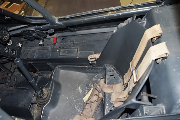
Continuing from the previous issue, the designer of this kit sent us an interesting note on the cockpit design.
I would like to share this valuable information base on his actual aircraft reserch.
Although these parts cannot be seen after completing the kit, we can imagine how much effort has been made to express the ultimate reality in the model.
In the last issue 129, I emphasized on an accurate construction of cockpit by using the left and right fuselage parts as jigs. If you are working on this kit right now, you know exactly what I mean.
In other words, if you follow the instruction manual that comes with the kit and glue to complete the cockpit parts, sometimes there is a slight misalignment in gluing, and that affects the overall dimensions later. There is a risk that the outer panels will not match up perfectly and have some gaps when you attach the cowling or the fuselage.
This is common in the world of aircraft modeling.
You might say so and just move on. However, in fact, the fuselage, cowlings, wing parts, and other parts of this kit are all made tightly and neatly.
Please take my word for it here.
"Use the left and right parts of the fuselage as assembly jigs and work precisely.”
▋While assembling the fuselage, you can imagine the original design concept of the Fw 190.
This fuselage design seems to be a conclusion that Kurt Tank reached to solve the difficult problem - how he could make a powerful single-engine and single-seated fighter with a star-shaped air-cooled engine that has a large projected area.
This very sophisticated fuselage design is superb. It must have had a great influence on the design of Japanese army and navy aircraft of the time.
Following the completion of the fascinating engine and the precise cockpit, it is time for more fun, the fuselage assembly.
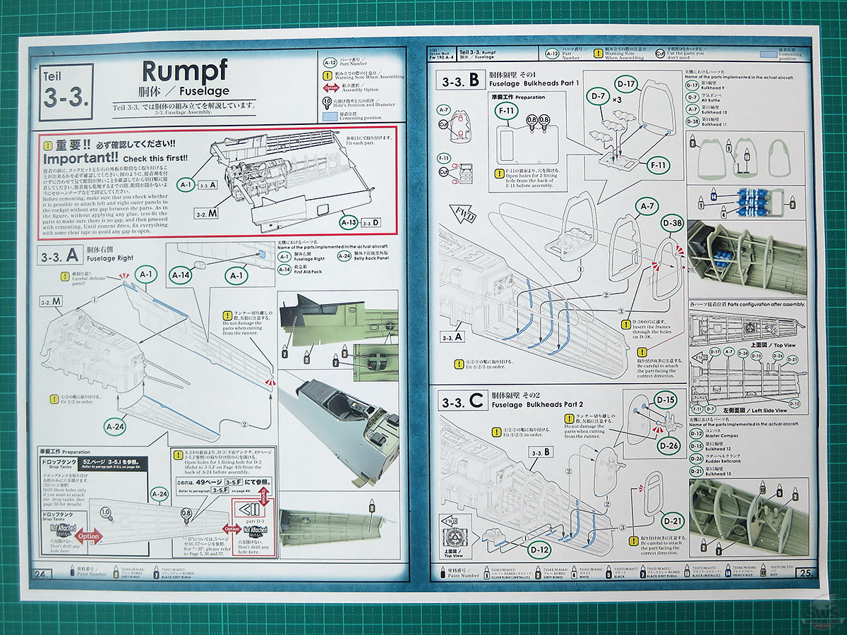
Firs of all, can you install the cockpits that you made precisely into the left and right fuselages?
If you used the fuselage parts as jigs, you must be happy and smiling with the cockpit and the fuselage fitting so perfectly.
Also, when gluing each bulkhead part, do not glue multiple parts at once, but work one part at a time by aligning the left and right parts of the fuselage.
Be careful not to damage the prongs on the front and back of the fuselage. (I accidentally damaged the tail part (in tears)).
In particular, you should be careful not to cut off the gluing area of the "crank" part that connects to the "rudder link".
Caution! Caution!
You have made various control devices of the Fw 190 up to this point. These cannot be seen in the end, but it is important that make it precisely in each step.
Wait, there is also an optional "drilling" on the lower fuselage. If you forget to do this, you will have a lot to do later.
▋This is a world first!?
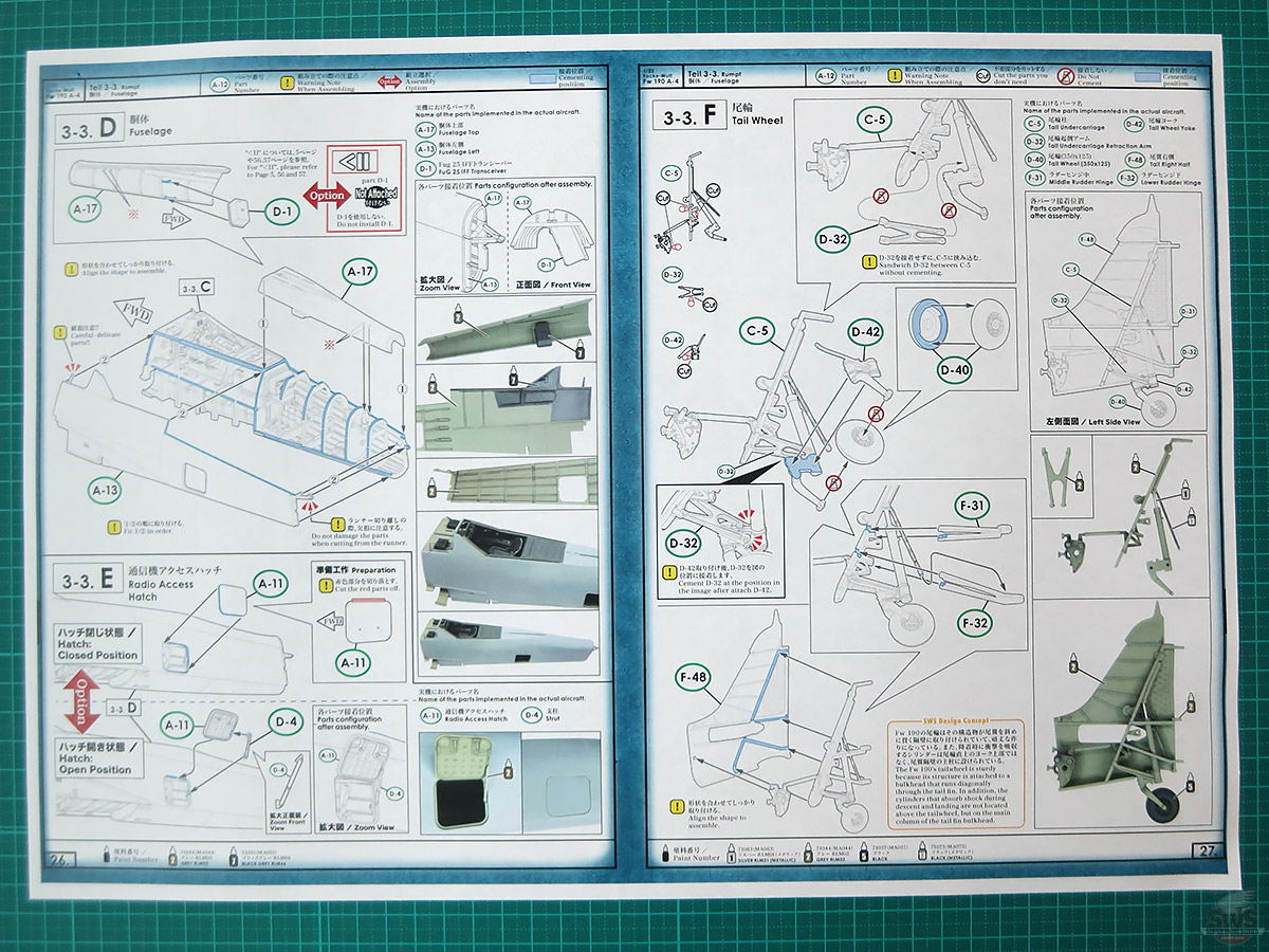
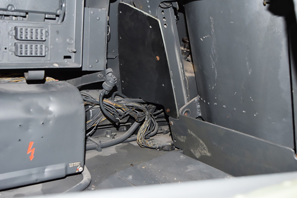
This is probably the first time in the world that the mechanism of the rear tailwheel of the Fw 190 has been reproduced so faithfully in a plastic model kit. I think the structure of retracting half of the tailwheel is very interesting.
The parts are made of plastic and are very delicate, so be careful not to damage them.
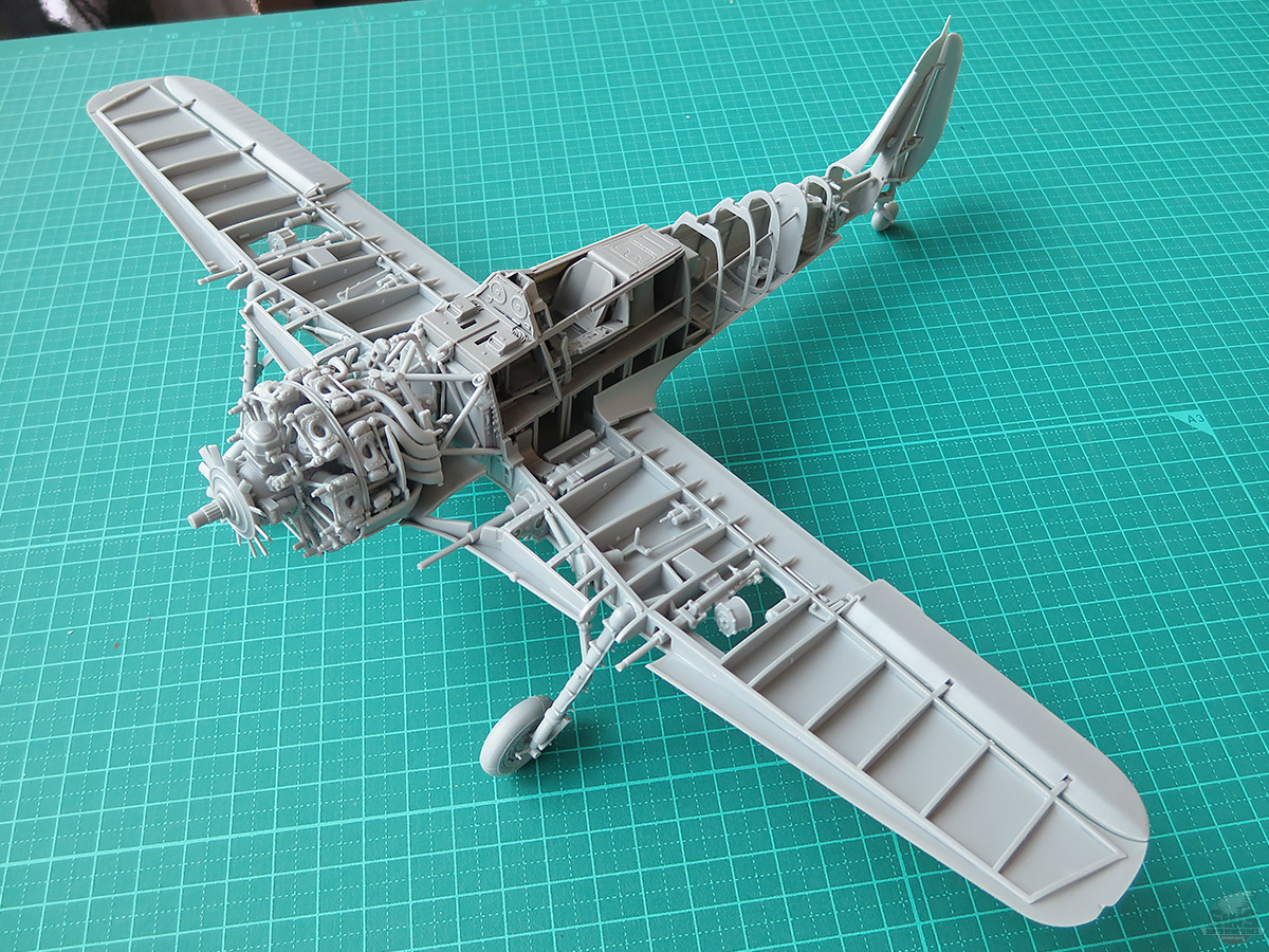
Now, the left and right fuselage parts fit perfectly with no gaps. Whew! Your skills are proven, top-notch! You have a choice whether to proceed to a completion, or to go with a naked model by leaving the internal structures visible as in the photo on this page… I know it's a tough decision, isn't it?
How about getting another kit to make both types? Sounds like a plan?
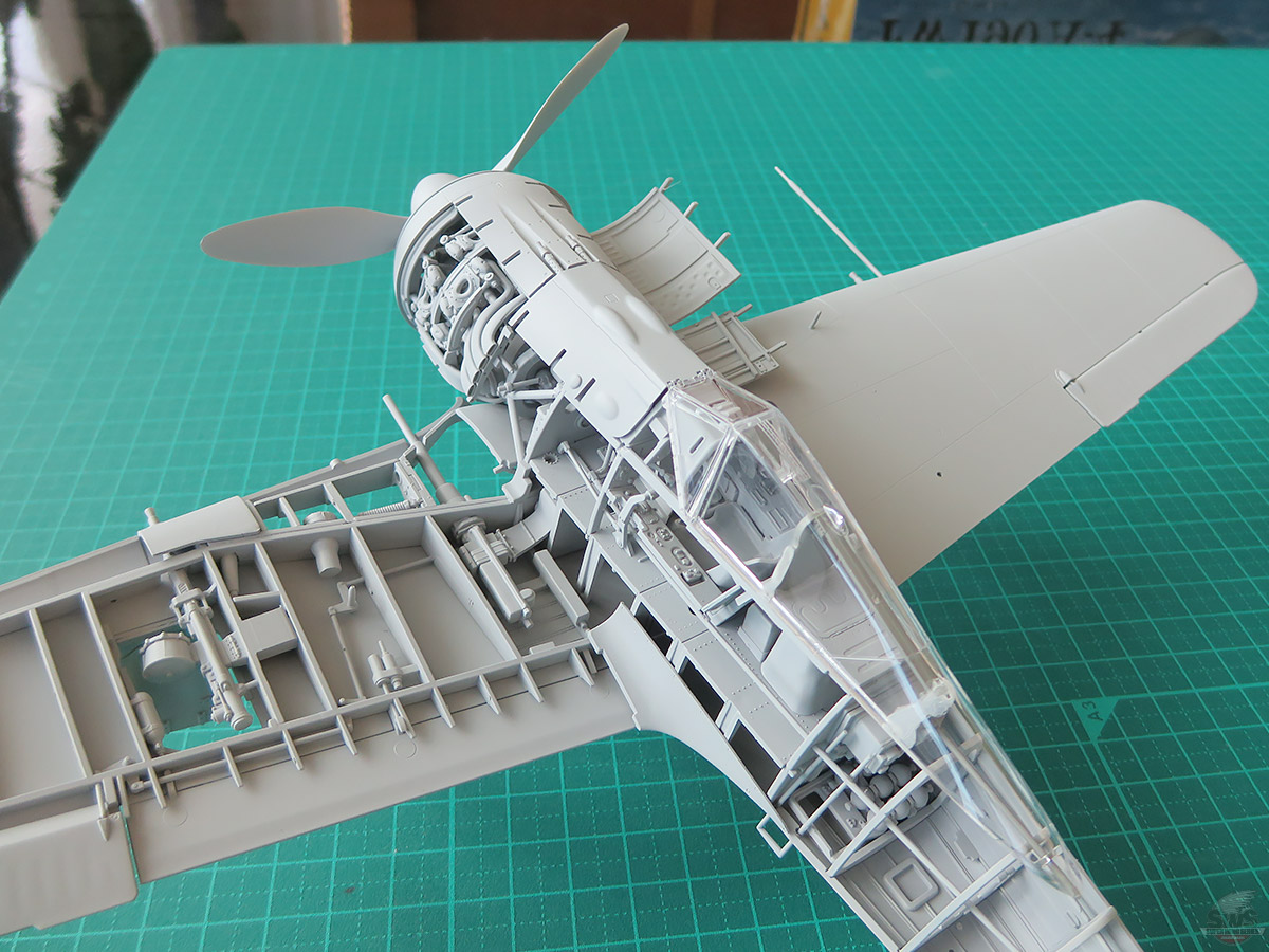
▋I went a little ahead and assembled the left half to be a naked type.
The solid, sturdy, but lightsome, as is typical of German planes, is now in front of my eyes.
Fw 190 fans would want to assemble more kits.
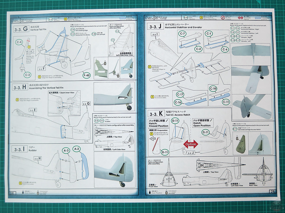
▋The rudder and the elevator will be accurately leveled and set vertically if you follow the instruction manual. At this point, it’s almost like building an actual aircraft. This looks as great as if you could put in on be a display.
▋Here is another photo; I went a bit ahead. This picture shows that the superb fighter plane was created by putting the BMW 801 D-2 engine, fuselage, wings, and cockpit together.
The Fw 190 is stunning!
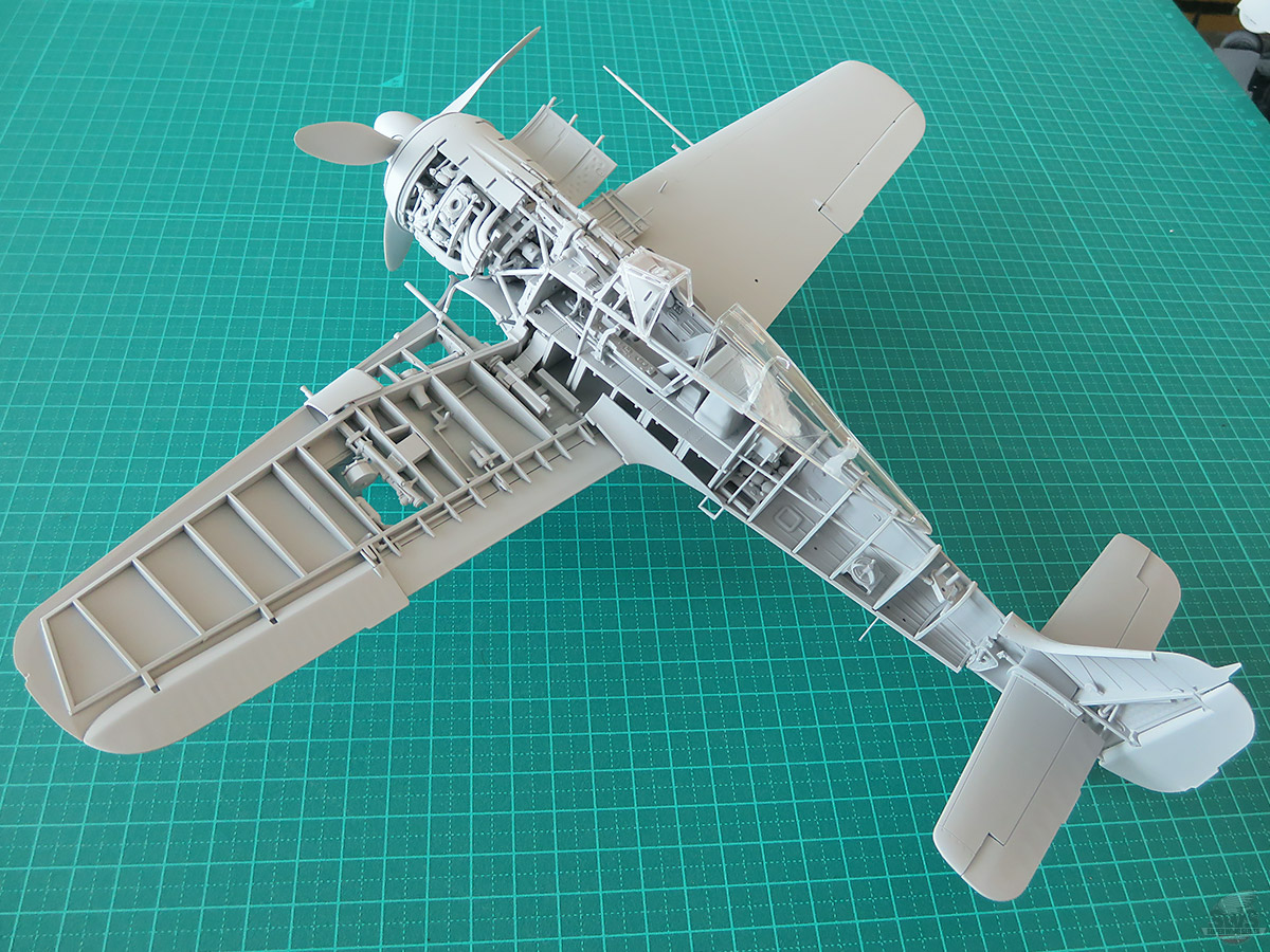
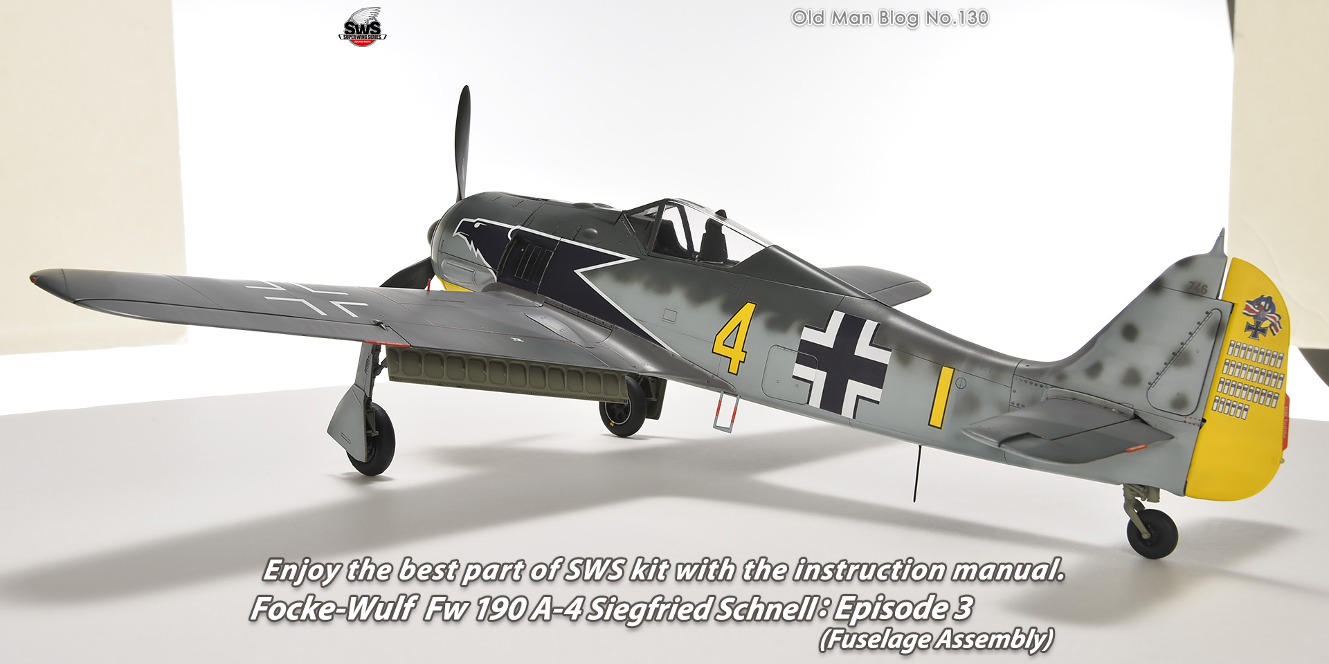
▋Look at the Fw 190, the world's premier single-seat fighter.
Its stylish and fascinating appearance must have changed the scenery of the air war.
See? This is the SWS kit.
The Fw 190 tailwheel device also reveals its structure in a detailed configuration.
Add some wire harnesses here to make it even more spectacular…no, you won’t see them, which is a real shame... but I believe you will do it.
The rudder and the elevator went smoothly. As usual, the horizontal and vertical are fine.
At this point, One can’t help but get enraptured by the beauty of the Fw 190’s form.
In the next issue, we will start from the main wings, join them to the fuselage and equip them with armament, and finally install the BMW engine.
Please look forward to the next issue of ~~~~!
Hideyuki Shigeta
President, Zoukei-Mura
![]()

 Old Man Blog No.129
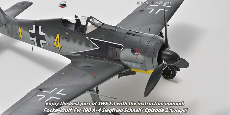
Enjoy the best part of SWS kit with the instruction manual. Focke-Wulf Fw 190 A-4 Siegfried Schnell: Episode 2 (Cockpit)
Old Man Blog No.129
Enjoy the best part of SWS kit with the instruction manual. Focke-Wulf Fw 190 A-4 Siegfried Schnell: Episode 2 (Cockpit)
 Old Man Blog No.131
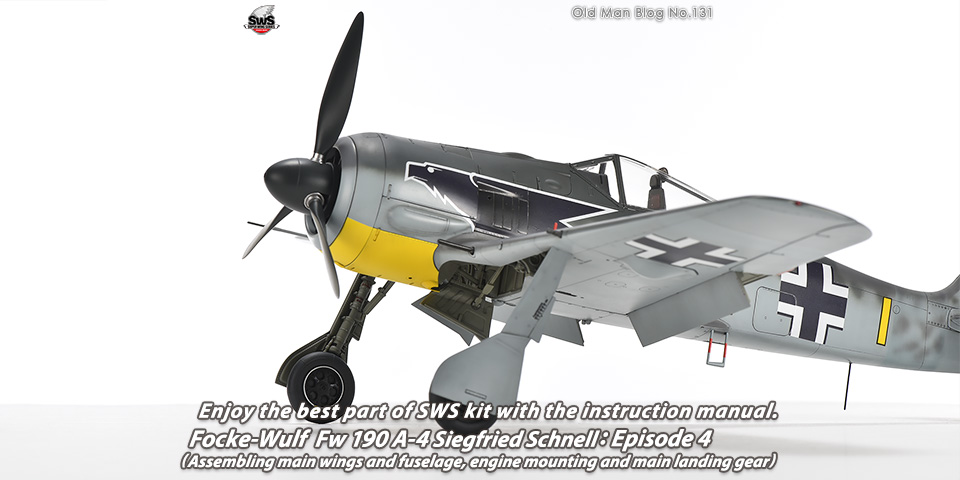
Enjoy the best part of SWS kit with the instruction manual. Focke-Wulf Fw 190 A-4 Siegfried Schnell: Episode 4 (Assembling main wings and fuselage, engine mounting and main landing gear)
Old Man Blog No.131
Enjoy the best part of SWS kit with the instruction manual. Focke-Wulf Fw 190 A-4 Siegfried Schnell: Episode 4 (Assembling main wings and fuselage, engine mounting and main landing gear)